Monday, May 17, 2010


We ride wednesday! Come and cheer us on at BCIT willingdon Campus. Assembly starts at 10, racing by noon, fun for the whole family all day!

Monday, May 10, 2010

The peices come together

Some photos of the peices coming together


Thursday, February 4, 2010

Funny-design stuff

Railroad tracks.


The standard railroad gauge (distance between the rails) is 4 feet, 8.5 inches. Why?

Because that's the way they built them in England.
Why did the English build them like that?

Because they used the same tools that they used for building wagons, which used that wheel spacing.

Why did the wagons have that particular wheel spacing?

Because that was the spacing of the wheel ruts on the roads in England & if they tried to use any other spacing, the wagon wheels would break.
So who built those old rutted roads?

Imperial Rome built the first long distance roads for their legions.

The roads have been used ever since.
Roman chariots formed the initial ruts, which everyone else had to match for fear of destroying their wagon wheels.

Since the chariots were made for Imperial Rome, they were all alike in the matter of wheel spacing. Therefore the standard railroad gauge of 4 feet, 8.5 inches is derived from the original specifications for an Imperial Roman war chariot.

The chariots were made just wide enough to accommodate the rear ends of two horses.


So the next time you are handed a specification/procedure/process and wonder 'What horse's ass came up with it?', you may be exactly right.


Now, a twist to the story :
When you see a Space Shuttle sitting on its launch pad, there are two big booster rockets attached to the sides of the main fuel tank. These SRB's are made at a factory in Utah. The Engineers who designed the SRB's would have preferred to make them bigger, but they had to be shipped by train. The railroad line from the factory runs through a tunnel in the mountains, and the SRB's had to fit through that tunnel. The tunnel is slightly wider than the railroad track, and the railroad track, as you now know, is about as wide as two horses' behinds.

So, a major Space Shuttle design feature, of what is arguably the world's most advanced transportation system, was determined over two thousand years ago by the width of a horse's ass.

Gives one a new perspective of a horse's ass.

Steering geometry

Tricycle steering geometry - introduction

Correct steering geometry is particularly important for human-powered vehicles, because if tyres scrub as you turn, the energy wasted can significantly slow you down. It can also end up being expensive in tyres! The design method often used to minimise this effect is also useful for lightweight electric or solar vehicles - in fact, pretty much any multitrack vehicle.

There are several aspects to steering design:

* First, you need to make sure the steering linkage turns the wheels at the correct angle when you go round corners: this is Ackermann steering geometry.
* Then, you may wish to minimise bump and brake steer by using what is known as centrepoint steering or zero scrub radius geometry, usually achieved by kingpin inclination (side-to-side).
* Also, for stability and a 'self-centring' effect, the front wheels must employ some 'caster effect' or 'trail'. This is usually achieved by inclining the kingpins fore-aft.
* Finally, there are a few other considerations, such as the type of handlebars to be employed, and some quick notes about detail design

In more detail:
Ackermann steering geometry

When a trike or quad goes round a corner, it turns around a point along the line of its rear axle. As the diagram shows, this means that the two front wheels will have to turn through slightly different angles so that they are also guiding the vehicle round this point, and not 'fighting' the turn by scrubbing. As the diagram below shows, the inside wheel turns through a greater angle than the outer.
Ackermann steering diagram

Ackermann geometry is simply steering which achieves this, keeping each front wheel at the correct angle, through the whole range of the steering motion.

Even with perfect Ackermann steering, there will still be some scrub, because of dynamic effects (the trike tries to go straight on, the tyres push it round the corner, so it tends to understeer). Some builders 'tweak' the Ackermann model to take account of this, usually by arranging that the wheels remain more close to parallel than exact Ackermann would suggest. Having said that, pure Ackermann works pretty well - and it doesn't have to be perfect.
Centrepoint steering

Look at most recumbent trikes from the front and you'll notice that the kingpins slope outwards, like this:
Centrepoint steering pic Centrepoint steering pic Images courtesy of ICE via the Trikes CD-ROM.

The idea is that the kingpin axis meets the ground at or near the contact point of the tyre - the so-called 'centre point'. The rather crudely-drawn red line on the diagram shows this.

Then if the wheel hits a bump, the forces from this impact will be in line with the turning axis, so no torque can be exerted which might jerk the steering. Also, if just one of the front wheels is braked, or the two front wheels are braked unevenly, the forces should again all pass through the kingpin axes and not affect the steering.

The kingpin inclination which is used to achieve this should be kept to a minimum to keep the steering from becoming heavy: the greater the angle, the more steering motion needs to lift the weight of the trike as you turn. Most builders keep the kingpin inclination to around say 15 degrees, preferably less.

Many designs have the kingpin axis hit the ground a little in from the exact centre of the tyre contact point: this gives a certain amount of 'road feel'. Others put the intersection of kingpin axis and ground outside the tyre contact point in an effort to reduce or eliminate brake steer.

Commercial manufacturers have done a lot of work refining their steering: some have virtually eliminated brake steer, and use separate braking systems for each front wheel, each one controlled by one of the rider's hands. Lack of brake steer makes this a practical arrangement, as the handling is relatively unaffected when braking with just one hand, such as when indicating.

Others link the front brakes using hydraulics, careful adjustment or mechanical linkages to balance the braking between the two front wheels, and controlling both front brakes from a single lever. Centrepoint steering is less critically important in this arrangement.
Caster, trail

Just like a two-wheeler, a trike's steering needs to self-centre if it's to handle well, and especially to be stable at speed. And just as on a two-wheeler, this is usually achieved by inclining the steering axis (the steerer tube on a bike).
Caster pic Caster pic Images courtesy of Greenspeed via the Trikes CD-ROM.

Clearly, this inclination is in a plane at right angles to the centrepoint steering inclination we've just mentioned: that is an angle seen as viewed from the front of the trike: the caster angle is as viewed from the side.

Around 10-14 degrees of kingpin caster inclination seems to work OK on most designs.

Caster effect can also be achieved with no kingpin inclination, offsetting the axle mounting points from the kingpin axis instead. Read up about 'trail' at, for example, Sheldon Brown's splendid website if you're interested. But most commercial trikes seem to just mount the axle right on the kingpin axis.
Other considerations

* There are various possible linkages which can be used to connect the two front wheels in a way which will give correct Ackermann - and also any number of ways by which you can connect the handlebars. Some possibilities are shown at Rick Horwitz' website. Use whichever seems appropriate for your design - but bear in mind that only certain of them are fully modelled in these spreadsheets - see later.
*

How 'twitchy' or 'slow' the steering feels largely depends on the 'steering ratio': how far the wheels turn relative to the handlebar movement. This is determined by the width of the bars, linkage (or direct connection) between the bars and the linkage between the two front wheels.

Ideally, in the middle of the steering motion (when you're going in a straight line) the steering should be relatively insensitive, for ease of control at speed. So a degree of handlebar movement has only a small effect on the steering.

But towards the extremes of the steering motion, which would only be used for low-speed manoeuvring, handlebar movement may as well make a big difference to steering direction.

In this way you can make the best use of available handlebar movement, which will be limited by space available.

In any case, wider bars will always make for more stable steering.
* The minimum diameter for an axle supported at one end only seems to be 12mm of hardened steel. Some MTB hubs have 12mm axles and bearings already: another possibility which avoids excessive machining is to use hubs with 20mm thru-axles, as used on some MTB suspension forks, or wheelchair hubs. Sturmey-Archer now make a rather neat quick-release drum brake one-sided hub for wheelchair use, which would also do fine on a trike.
*

Toe-in or toe-out is usually not necessary for human-powered vehicles: usually all either achieves is to slow you down and scrub your tyres away. Having said that, some users of various commercial designs have found beneficial effects on handling at speed.

To measure toe-in or toe-out (also known as tracking) you can simply use a tape measure from rim to rim at front and back - for zero toe-in the distances should be equal. Various other methods are also possible of course.

Sometimes a little toe-in or toe-out is recommended so that as any slack/flex in the steering is taken up by the rolling resistance and rider's weight, the wheels come perfectly parallel. Definitely worth doing if your linkage is a bit sloppy.
*

It's occasionally suggested that the wheels be tilted out at the bottom (known as camber): the idea is that the outside wheel is then better able to withstand cornering forces, and the wider track will also enhance stability.

However, almost all commercial machines and the vast majority of home-builts just have the wheels vertical: this seems strongest and simplest all round. Tilted wheels are weaker; kingpin design becomes harder if you want zero scrub radius steering, and tyres wear on the sides rather than on the usually thicker top.

Steering home -- Next: the spreadsheets

Wednesday, January 27, 2010

suspension on trike


front wheel drive trike

Next Stage of Development

We have established a design to follow basically consisting of the front end of a adult mountain bike with two full suspension bikes added out behind.

The rear rider will be powering the rear wheels by way of the main bike bottom bracket drive system. The rear wheels will be attached on a through axle mounted in the two sets of drop outs in back.

The front rider will power the front wheel with a direct drive, much like a children s tricycle. Drawings and 3d model to follow.

Our Community Bikes on Main has been able to hook us up with components and goodies that will make this whole process easy peasey

Thursday, January 21, 2010

old school....not such a new idea?


suspension tandem tricycle


http://www.motoredbikes.com/phpBB2/userpix/57_tandem_tricycle1_2.jpg

lol

???


tandem tricycle...tadpole style?

M. Steel Cycles
Tandem Bicycle to Tandem Trike Convertible


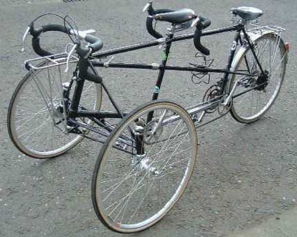
A Newton tandem tricycle conversion, but that's not all....


This was a job undertaken for one of our customers who wanted a little more stability. As the tandem already had S&S couplings it seemed logical to utilize them to fasten the tricycle conversion on. This was certainly one of the more 'interesting' jobs we have tackled.

The tricycle front end is held on with S&S couplings. This allows the normal front end to be replaced should the customer require it.

3 nuts, 3 cable connectors and off it comes.

http://www.sandsmachine.com/a_mst_t1.htm

adventure tandem tricycle


The Adventurer Tandem, model ATP 2600, is a tandem tricycle designed for use by adults with mobility, balance, or neurological disabilities. This tandem cycle features a tubular steel frame, a wide rear stance for added stability, seven speeds, and two seats. The driver steers and controls the cycle from the rear, and the person with a disability sits in the front. The front seat and the front handlebar height are adjustable, and the front handlebar can be moved out of the way for dismounting. The front seat is available with a seat belt in low- and high-back models. The cycle also features a crank and sprocket that can be adjusted to accommodate different hip and foot positions. Other features include locking hand brakes and quick release bolts for disassembly and transport. This cycle accommodates riders with 22-inch inseams. DIMENSIONS: The cycle has a 40-inch rear stance


http://www.freedomconcepts.com
.

different ways to set up a tandem...

http://www.sheldonbrown.com/tandem2.html


Phase

Most tandems are set up so that the stoker's and pilot's cranks and pedals are syncronized. When the pilot's left crank is at the top of its rotation, the stoker's left crank is also straight up. This condition is called having the cranks "in phase."

Some tandemists prefer a different setup, in which the cranks are "out of phase." The most common alternate setup is for the pilot's cranks to be horizontal while the stoker's cranks are vertical. This is called "90 degrees out of phase" because the cranks are at a 90 degree angle to one another. If the captain's cranks are 90 degrees forward of the stoker's cranks, we say the captain's cranks are leading by 90 derees.

In phaseOut of phase
Both riders move together, for more of a "team" feel.
Slow-speed handling is better.

Less risk of striking a pedal on the road while turning, because both inside cranks can be in the up position at the same time.

Power is applied to the wheels in pulses. When both cranks are vertical, little power can be applied, which can cause the tandem to stall in a steep climb.

Standing to pedal is easier when both riders move together.

Riders move differently from one another, as each is in a different part of the power stroke.

The pilot must remember where his stoker's pedals are in a turn.

Power is applied in a smooth flow, because while one set of cranks is at dead center, the other is in the heart of its power stroke.

This can help in steep climbs, and also reduces stress to some drive-train parts, since both riders are never applying full power at the same time.

"There are essentially three entities riding a tandem:
The captain, the stoker, and the spirit.
It is the spirit who likes in-phase cranks."
--Osman Isvan

Cranks and Cadence

Any tandem team needs to come to terms with the cadence issue. With practice and patience, most couples can work this out on a standard tandem. Some teams, particularly those who are not well-matched in leg length or pedaling style may need to go to a technical fix.

Different-Length Cranks

The simplest way to accommodate disparate cadence preferences is to install different length cranks for the stoker and for the pilot.

In general, for any given rider, the shorter the cranks are, the easier it becomes to spin a rapid cadence. If the rider who prefers a faster cadence gets longer cranks, this will develop a preference for a slightly slower cadence. If the rider who prefers a slower cadence gets shorter cranks, it will become easier to pedal at a faster rate. The most common crank length is 170 mm. This is what comes stock on most tandems. If you find that you have serious cadence incompatibility, start by installing 175 mm cranks for the rider who wants a faster cadence. If this helps, but not enough, get 165 mm cranks for the rider who has trouble pedaling fast.

Note, changing the crank length doesn't directly change the cadence, and both riders will still be pedaling at the same cadence, but the longer cranks will encourage the "spinner" to slow down a bit, and the shorter cranks will make it easier for the "slogger" to keep up.

Independent Gearing/Coasting.

But what about giving each rider the option of shifting to a different gear than that used by the other? What about giving one or both riders the option of coasting while the other continues to pedal?

Both of these options are possible, and available, but not on standard tandems. With tandems of conventional geometry, the cranks must move at the same speed, because if not, the time will come when one the pilot's left crank is pointing backward, while the stoker's left crank is facing forward, and their feet will collide!

To make independent gearing/independent coasting work, you either need a tandem with a longer than usual spacing between the riders, or a recumbent.

Independent gearing/independent coasting does add to the complexity and weight of a tandem, but for some riders it is worth the cost.

tandem technique

Good to know...

http://sheldonbrown.com/tandem.html

tandem gearing


http://www.bikexprt.com/bicycle/tancrank.htm

building a differential

http://www.youtube.com/watch?v=K4JhruinbWc

Tuesday, January 19, 2010

ANOTHER OFF ROAD QUAD

http://www.lightfootcycles.com/handcrankatc.php


WEB-SITE: SORRY, DIDN'T PUT HYPER LINK ON LAST FEW POSTS.

SUSPENSION INFO--NOMENCLATURE

HOW STUFF WORKS

http://auto.howstuffworks.com/car-suspension.htm


Spring rate
Further information: Spring rate

The spring rate (or suspension rate) is a component in setting the vehicle's ride height or its location in the suspension stroke. Vehicles which carry heavy loads will often have heavier springs to compensate for the additional weight that would otherwise collapse a vehicle to the bottom of its travel (stroke). Heavier springs are also used in performance applications where the loading conditions experienced are more extreme.

Springs that are too hard or too soft cause the suspension to become ineffective because they fail to properly isolate the vehicle from the road. Vehicles that commonly experience suspension loads heavier than normal have heavy or hard springs with a spring rate close to the upper limit for that vehicle's weight.

Travel

Travel is the measure of distance from the bottom of the suspension stroke (such as when the vehicle is on a jack and the wheel hangs freely), to the top of the suspension stroke (such as when the vehicles wheel can no longer travel in an upward direction toward the vehicle). Bottoming or lifting a wheel can cause serious control problems or directly cause damage. "Bottoming" can be either the suspension, tires, fenders, etc. running out of space to move or the body or other components of the car hitting the road. The control problems caused by lifting a wheel are less severe if the wheel lifts when the spring reaches its unloaded shape than they are if travel is limited by contact of suspension members.

Damping

Damping is the control of motion or oscillation, as seen with the use of hydraulic gates and valves in a vehicles shock absorber. This may also vary, intentionally or unintentionally. Like spring rate, the optimal damping for comfort may be less than for control.

Damping controls the travel speed and resistance of the vehicles suspension. An undamped car will oscillate up and down. With proper damping levels, the car will settle back to a normal state in a minimal amount of time. Most damping in modern vehicles can be controlled by increasing or decreasing the resistance to fluid flow in the shock absorber.

Camber control

See dependent and independent below.

Camber changes due to wheel travel, body roll and suspension system deflection or compliance. In general, a tire wears and brakes best at -1 to -2 degrees of camber from vertical. Depending on the tire and the road surface, it may hold the road best at a slightly different angle. Small changes in camber, front and rear, can be used to tune handling. Some race cars are tuned with -2~-7 degree camber depending on the type of handling desired and the tire construction. Oftentimes, too much camber will result in the decrease of braking performance due to a reduced contact patch size through excessive camber variation in the suspension geometry. The amount of camber change in bump is determined by the instantaneous front view swing arm (FVSA) length of the suspension geometry, or in other words, the tendency of the tire to camber inward when compressed in bump.

Beach Raider


I've e-mailed the builder of these trikes. He thinks we need to have 4 wheels. He said


"if you want to make a tandem where you sit one behind the other you may be able to use them. a side by side trike would require a completely different approach. if you are on trails you would be better off with 4 wheels to distribute the load over the softer trail. you are not on a hard surface. you could add bigger brakes like a go cart brake on the rear axle. remember you will have the weight of 2 people and the weight of the quad to stop."


I've got the plans, so we can adapt parts.

Mountain Quad


DESIGN

http://www.crank-it.com/quaddesign.html

SPECIFICATIONS

http://www.crank-it.com/quadspecs.html

FEATURES

http://www.crank-it.com/quadfeatures.html

Wednesday, January 13, 2010

stair master idea


http://www.conradstoltz.com/interbike-last-vegas-dirt-demo/

Tuesday, January 12, 2010

Mind map, not


Accessory Ideas

http://www.lightfootcycles.com/special.php

• Blender
• Water pump
• Chain saw
• Fire starter
• Light/flashlight
• Battery charger/
• Fan
• Something to do with beer
• Coffee maker

Saturday, January 9, 2010

Wheel stablizer


http://www.fatwheels.com/

http://www.stabilizerwheels.com/

http://www.pointsincase.com/blog/uploaded_images/training_wheels-748506.jpg

Wednesday, January 6, 2010

Personal Log template?

Personal Log

In Class Activity

Out of Class Activity

Insights/Learning

Group Dynamics

Links to multi-wheeled bikes

http://www.bhsi.org/fourwhel.htm

Four Cross


Rough Riderz UK

Check out these vehicles!

Mud Chaps take off!

This is the base camp set up and design archive for the Mud Chaps team of the BCIT - TTED Projects Challenge. We will be designing and building an off road human powered vehicle to compete in a race challenge on may 19th.